555 Timer Schematic Symbol : 555 Timer Pinout Voltage Controlled Oscillator Basic Electronic Circuits Timer / For example, you might put a transistor on the output pin of a 555 timer ic (which produces a variable timing pulse), or a shift register ic (which allows you to produce multiple control signals in parallel) to control high current loads from those devices.
555 Timer Schematic Symbol : 555 Timer Pinout Voltage Controlled Oscillator Basic Electronic Circuits Timer / For example, you might put a transistor on the output pin of a 555 timer ic (which produces a variable timing pulse), or a shift register ic (which allows you to produce multiple control signals in parallel) to control high current loads from those devices.. Connect the switch link (red link in the photo) to the bottom rail. This will require a junction. The internal block diagram and schematic of the 555 timer are highlighted with the same color across all three drawings to clarify how the chip is implemented: To add a junction, you can do it in one of two ways: Between the positive supply voltage v cc and the ground gnd is a voltage divider consisting of three identical resistors, which create two reference voltages at 1 ⁄ 3 v cc and 2.
There is no 555 timer though, so let's create our own. As we mentioned above, adding junctions to your schematic allows intersecting nets to share an electrical connection. In monostable mode, the duration for which the pin 3 would remain high, is given by the below formulae: We need to set 555 timer in monostable mode to build timer. Connect the switch link (red link in the photo) to the bottom rail.
555 Timer Ic Block Diagram Working Pin Out Configuration Data Sheet from www.circuitstoday.com For example, you might put a transistor on the output pin of a 555 timer ic (which produces a variable timing pulse), or a shift register ic (which allows you to produce multiple control signals in parallel) to control high current loads from those devices. Try using a different value capacitor in the circuit to see the time period change. T = 1.1 * r1*c1. This will require a junction. After the timer has finished timing or timed out, the led will switch on again. As we mentioned above, adding junctions to your schematic allows intersecting nets to share an electrical connection. To add a junction, you can do it in one of two ways: In monostable mode, the duration for which the pin 3 would remain high, is given by the below formulae:
T = 1.1 * r1*c1.
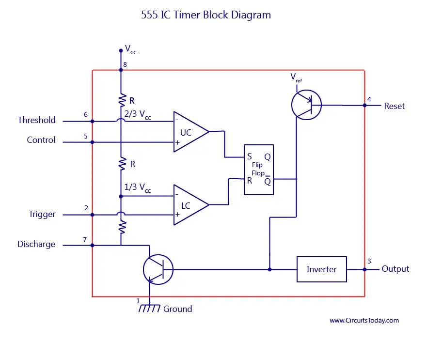
As we mentioned above, adding junctions to your schematic allows intersecting nets to share an electrical connection. This will require a junction. The internal block diagram and schematic of the 555 timer are highlighted with the same color across all three drawings to clarify how the chip is implemented: Connect the switch link (red link in the photo) to the bottom rail. Same as adding the schematic, just add a schlib to the project and watch it fall underneath "libraries" inside your project. Between the positive supply voltage v cc and the ground gnd is a voltage divider consisting of three identical resistors, which create two reference voltages at 1 ⁄ 3 v cc and 2. For example, you might put a transistor on the output pin of a 555 timer ic (which produces a variable timing pulse), or a shift register ic (which allows you to produce multiple control signals in parallel) to control high current loads from those devices. We need to set 555 timer in monostable mode to build timer. Jul 27, 2012 · close the switch to start the timer. T = 1.1 * r1*c1. There is no 555 timer though, so let's create our own. In monostable mode, the duration for which the pin 3 would remain high, is given by the below formulae: Frank silavwe on bc547 transistor project
We need to set 555 timer in monostable mode to build timer. We need to add a net that connects between pin 3 on our 555 timer and our r3 and r4 resistors. Connect the switch link (red link in the photo) to the bottom rail. Frank silavwe on bc547 transistor project The editor is fairly straightforward and has tons of hotkeys associated with it to make it easy when creating a component with several pins.
Blink Two Leds Alternatively With 555 Ic Classic Ic Circuit Diagram Ii from thecustomizewindows.com Frank silavwe on bc547 transistor project So to build 1 minute (60 seconds) timer we need resistor of value 55k ohm and capacitor of 1000uf: Connect the switch link (red link in the photo) to the bottom rail. Jul 27, 2012 · close the switch to start the timer. As we mentioned above, adding junctions to your schematic allows intersecting nets to share an electrical connection. This will require a junction. Same as adding the schematic, just add a schlib to the project and watch it fall underneath "libraries" inside your project. Jul 14, 2015 · all we need to change the value of resistor r1 and/or capacitor c1.
In monostable mode, the duration for which the pin 3 would remain high, is given by the below formulae:
To add a junction, you can do it in one of two ways: Jul 14, 2015 · all we need to change the value of resistor r1 and/or capacitor c1. There is no 555 timer though, so let's create our own. Try using a different value capacitor in the circuit to see the time period change. Connect the switch link (red link in the photo) to the bottom rail. The editor is fairly straightforward and has tons of hotkeys associated with it to make it easy when creating a component with several pins. Between the positive supply voltage v cc and the ground gnd is a voltage divider consisting of three identical resistors, which create two reference voltages at 1 ⁄ 3 v cc and 2. T = 1.1 * r1*c1. This will switch the led off and start the timer. In monostable mode, the duration for which the pin 3 would remain high, is given by the below formulae: For example, you might put a transistor on the output pin of a 555 timer ic (which produces a variable timing pulse), or a shift register ic (which allows you to produce multiple control signals in parallel) to control high current loads from those devices. Frank silavwe on bc547 transistor project So to build 1 minute (60 seconds) timer we need resistor of value 55k ohm and capacitor of 1000uf:
Jul 14, 2015 · all we need to change the value of resistor r1 and/or capacitor c1. So to build 1 minute (60 seconds) timer we need resistor of value 55k ohm and capacitor of 1000uf: There is no 555 timer though, so let's create our own. We need to set 555 timer in monostable mode to build timer. Connect the switch link (red link in the photo) to the bottom rail.
555 Timer Delay Circuits Electronic Schematics Electronics Circuit Electronics Basics from i.pinimg.com For example, you might put a transistor on the output pin of a 555 timer ic (which produces a variable timing pulse), or a shift register ic (which allows you to produce multiple control signals in parallel) to control high current loads from those devices. Jul 27, 2012 · close the switch to start the timer. As we mentioned above, adding junctions to your schematic allows intersecting nets to share an electrical connection. There is no 555 timer though, so let's create our own. In monostable mode, the duration for which the pin 3 would remain high, is given by the below formulae: Same as adding the schematic, just add a schlib to the project and watch it fall underneath "libraries" inside your project. We need to add a net that connects between pin 3 on our 555 timer and our r3 and r4 resistors. Try using a different value capacitor in the circuit to see the time period change.
There is no 555 timer though, so let's create our own.
We need to set 555 timer in monostable mode to build timer. Connect the switch link (red link in the photo) to the bottom rail. The internal block diagram and schematic of the 555 timer are highlighted with the same color across all three drawings to clarify how the chip is implemented: For example, you might put a transistor on the output pin of a 555 timer ic (which produces a variable timing pulse), or a shift register ic (which allows you to produce multiple control signals in parallel) to control high current loads from those devices. Jul 14, 2015 · all we need to change the value of resistor r1 and/or capacitor c1. The editor is fairly straightforward and has tons of hotkeys associated with it to make it easy when creating a component with several pins. Same as adding the schematic, just add a schlib to the project and watch it fall underneath "libraries" inside your project. So to build 1 minute (60 seconds) timer we need resistor of value 55k ohm and capacitor of 1000uf: Between the positive supply voltage v cc and the ground gnd is a voltage divider consisting of three identical resistors, which create two reference voltages at 1 ⁄ 3 v cc and 2. As we mentioned above, adding junctions to your schematic allows intersecting nets to share an electrical connection. Frank silavwe on bc547 transistor project After the timer has finished timing or timed out, the led will switch on again. There is no 555 timer though, so let's create our own.
We need to add a net that connects between pin 3 on our 555 timer and our r3 and r4 resistors 555 timer schematic. Jul 14, 2015 · all we need to change the value of resistor r1 and/or capacitor c1.


0 Komentar